Product Summary
The HD64F2633F25V is a microcomputer. It has an internal 32-bit architecture. The device is provided with sixteen 16-bit general registers and a concise, optimized instruction set designed for high-speed operation, and can address a 16-Mbyte linear address space. The HD64F2633F25V is also possible to incorporate an on-chip PC bus interface(IIC)*2 as an option. Four operating modes, modes 4 to 7, are provided, and there is a choice of single-chip mode or external expansion mode. The HD64F2633F25V is equipped with peripheral functions on-chip.
Parametrics
HD64F2633F25V absolute maximum ratings: (1)Power supply voltage:–0.3V to +4.3V ; (2)Input voltage (XTAL, EXTAL, OSC1, OSC2):–0.3V to VCC +0.3V ; (3)Input voltage (ports 4 and 9):–0.3V to AVCC +0.3V ; (4)Input voltage (except XTAL, EXTAL, OSC1, OSC2, ports 4 and 9):–0.3V to PVCC +0.3V ; (5)Reference voltage:–0.3V to AVCC +0.3V ; (6)Analog power supply voltage:–0.3V to +7.0V ; (7)Analog input voltage:–0.3V to AVCC +0.3V ; (8)Operating temperature: Regular specifications:–20℃ to +75℃, Wide-range specifications:–40℃ to +85℃; (9)Storage temperature:–55℃ to +125℃.
Features
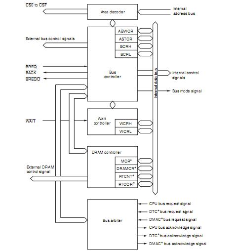
HD64F2633F25V features: (1)Address space divided into 8 areas, with bus specifications settable independently for each area ; (2)Choice of 8-bit or 16-bit access space for each area ; (3)2-state or 3-state access space can be designated for each area ; (4)Number of program wait states can be set for each area ; (5)Burst ROM directly connectable ; (6)Possible to connect a maximum of 8 MB of DRAM (alternatively, it is also possible to use an interval timer) ; (7)External bus release function; (8)Supports debugging functions by means of PC break interrupts ; (9)Two break channels ; (10)Sixty-nine basic instructions ; (11)8/16/32-bit move/arithmetic and logic instructions ; (12)Unsigned/signed multiply and divide instructions ; (13)Multiply-and accumulate instruction ; (14)Powerful bit-manipulation instructions; (15)6-channel 16-bit timer on-chip ; (16)Pulse I/O processing capability for up to 16 pins; (17)Automatic 2-phase encoder count capability; (18)Maximum 16-bit pulse output possible with TPU as time base ; (19)Output trigger selectable in 4-bit groups ; (20)Non-overlap margin can be set ; (21)Direct output or inverse output setting possible.
Diagrams

 |
 HD6412240TE13 |
 |
 IC H8S MPU ROMLESS 100TQFP |
 Data Sheet |
 Negotiable |
|
||||
 |
 HD6412322RVF25 |
 |
 IC H8S MCU ROMLESS 128-QFP |
 Data Sheet |
 Negotiable |
|
||||
 |
 HD6412322RVFBL25 |
 |
 IC H8S MCU ROMLESS 128-QFP |
 Data Sheet |
 Negotiable |
|
||||
 |
 HD6412332VFCBL25 |
 Renesas Technology America |
 IC H8S MCU ROMLESS 144-QFP |
 Data Sheet |
 Negotiable |
|
||||
 |
 HD6412350F20 |
 |
 IC H8S MPU ROMLESS 5V 128QFP |
 Data Sheet |
 Negotiable |
|
||||
 |
 HD6412350F20V |
 |
 IC H8S MPU ROMLESS 5V 128QFP |
 Data Sheet |
 Negotiable |
|
||||
 (China (Mainland))


